The electric field represents the change in space around an electric charge. It is represented by lines called power lines.
This subject is part of the electrostatic content. So, take advantage of the exercises that Toda Matéria has prepared for you, test your knowledge and clear up doubts by following the commented resolutions.
Issues resolved and commented on
1) UFRGS - 2019
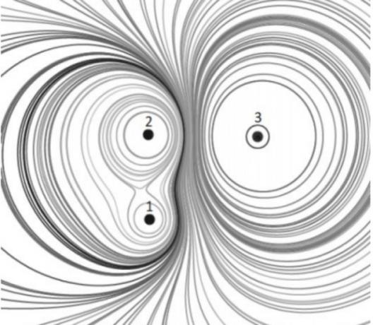
The figure below shows, in cross-section, a system of three electrical charges with their respective set of equipotential surfaces.

Check the alternative that correctly fills in the blanks in the statement below, in the order in which they appear. From the equipotential tracing, it can be stated that the loads... have signs... and that the load modules are such that... .
a) 1 and 2 – equal – q1 b) 1 and 3 – equal – q1 c) 1 and 2 – opposite – q1 d) 2 and 3 – opposite – q1 > q2 > q3
e) 2 and 3 – equal – q1 > q2 > q3
Equipotential surfaces represent surfaces formed by points that have the same electrical potential.
Observing the drawing we identified that between charges 1 and 2 there are common surfaces, this happens when the charges have the same sign. Therefore, 1 and 2 have equal charges.
From the drawing, we also observe that load 1 is the one with the smallest load modulus, as it has the smallest number of surfaces, and load 3 is the one with the highest number.
Therefore, we have to q1
Alternative: a) 1 and 2 - equal - q1
In the illustration, points I, II, III and IV are represented in a uniform electric field.

A particle with negligible mass and positive charge acquires the highest electrical potential energy possible if placed at the point:
there
b) II
c) III
d) IV
In a uniform electric field, a positive particle has greater electrical potential energy the closer it is to the positive plate.
In this case, point I is where the load will have the greatest potential energy.
Alternative: a) I
Electrostatic precipitator is equipment that can be used to remove small particles present in exhaust gases in industrial chimneys. The basic operating principle of the equipment is the ionization of these particles, followed by removal by the use of an electric field in the region where they pass. Suppose one of them has mass m, acquires a charge of value q and is subjected to an electric field of modulus E. The electrical force on this particle is given by
a) mqE.
b) mE/qb.
c) q/E.
d) qE.
The intensity of the electric force acting on a charge located in a region where there is an electric field is equal to the product of the charge by the magnitude of the electric field, that is, F = q. AND.
Alternative: d) qE
In a physics laboratory class, to study properties of electrical charges, an experiment was carried out in which small electrified spheres are injected into the upper part of a chamber, in a vacuum, where there is a uniform electric field in the same direction and direction as the local acceleration of the gravity. It was observed that, with an electric field of a modulus equal to 2 x 10³ V/m, one of the spheres, of mass 3.2 x 10⁻¹⁵ kg, remained at constant speed inside the chamber. This sphere has (consider: electron charge = - 1.6 x 10⁻¹⁹ Ç; proton charge = + 1.6 x 10⁻¹⁹ Ç; local acceleration of gravity = 10 m/s2)
a) the same number of electrons and protons.
b) 100 more electrons than protons.
c) 100 electrons less than protons.
d) 2000 more electrons than protons.
e) 2000 electrons less than protons.
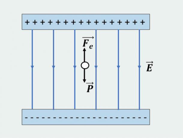
According to the information in the problem, we identified that the forces acting on the sphere are the weight force and the electrical force.
As the sphere remains in the chamber with constant velocity, we conclude that these two forces have the same magnitude and opposite direction. As the image below:

In this way, we can calculate the modulus of the load by equaling the two forces acting on the sphere, that is:
Now, to find the number of extra particles, let's use the following relationship:
q = n.e
being,
n: number of extra electrons or protons
e: elementary charge
Therefore, replacing the values indicated in the problem, we have:
As we have seen, the electric force will have to have the opposite direction from the weight force.
For this to occur it is necessary that the charge has a negative sign, because in this way the electric force and the electric field will also have opposite directions.
Therefore, the sphere will have to have a greater number of electrons than protons.
Alternative: b) 100 more electrons than protons.
5) Unesp - 2015
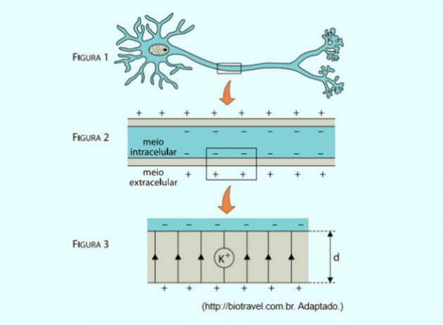
Electric models are often used to explain the transmission of information in various systems in the human body. The nervous system, for example, is composed of neurons (figure 1), cells delimited by a thin lipoprotein membrane that separates the intracellular environment from the extracellular environment. The inner part of the membrane is negatively charged and the outer part has a positive charge (figure 2), similar to what happens in the plates of a capacitor.

Figure 3 represents an enlarged fragment of this membrane, of thickness d, which is under the action of a field uniform electric, represented in the figure by its lines of force parallel to each other and oriented to up. The potential difference between the intracellular and extracellular medium is V. Considering the elementary electric charge as e, the potassium ion K+, indicated in figure 3, under the action of this electric field, would be subjected to an electric force whose module can be written as
In a uniform electric field the potential difference is given by:
The electric field E is equal to the ratio between the electric force and the charge, that is:
Replacing this relationship in the previous relationship, we have:
Since we only have one potassium ion, the expression q =n.e will become q=e. Substituting this value in the previous expression and isolating the force, we find:
Alternative: d)
The region between two flat and parallel metal plates is shown in the figure on the side. The dashed lines represent the uniform electric field existing between the plates. The distance between the plates is 5 mm and the potential difference between them is 300 V. The coordinates of points A, B and C are shown in the figure. (Write and Adopt: The system is in a vacuum. Electron charge = -1.6.10-19 Ç)

Determine
a) modules ANDTHE, ANDB and isÇ of the electric field at points A, B and C, respectively;
b) potential differences VAB and VBC between points A and B and between points B and C, respectively;
c) the work performed by the electrical force on an electron moving from point C to point A.
a) As the electric field between the plates is uniform, the value will be the same at points A, B and C, ie, ETHE = ANDB = ANDÇ = And .
To calculate the modulus of E, we will apply the following formula:
V= E.d
Where V = 300 V and d = 5 mm = 0.005 m, we will find the following value:
b) To calculate the potential differences of the indicated points, we will apply the same formula as above, considering the indicated distances, that is:
Now let's calculate the potential difference between points B and C. For this, note that these two points are at the same distance from the plates, that is, dBC = 0,004 - 0,004 = 0.
In this way, the potential difference will be equal to zero, that is:
VBC = 60 000. 0 = 0
c) To calculate the work, we will use the following formula:
If the potential of point C is equal to that of point B, then Vç - VTHE = VB - VTHE = - VAB = - 180 V. Substituting this value in the formula, we have:
Consider the electric field generated by two point-shaped electric charges, of equal values and opposite signs, separated by a distance d. About this electric field vector at the equidistant points of the charges, it is correct to state that
a) has the direction perpendicular to the line joining the two charges and the same direction at all these points.
b) has the same direction as the line that joins the two loads, but varies in direction for each point analyzed.
c) has a direction perpendicular to the line that joins the two loads, but varies in direction for each point analyzed.
d) has the same direction as the line joining the two charges and the same direction at all these points.
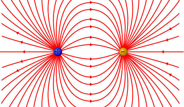
In the image below are represented the lines of force when we have two electrical charges with opposite signals.

As the electric field vector tangents the lines of force at each point, we verify that at the points equidistant from the charges the vector will have the same direction as the line joining the two charges and the same sense.
Alternative: d) has the same direction as the line joining the two charges and the same direction at all these points.
For more exercises, see also:
- Electric Charge: Exercises
- Electrostatics: Exercises
- Coulomb's Law: Exercises
- Resistor Association - Exercises


