
Resistors are elements of an electrical circuit that transform electrical energy into heat. When two or more resistors appear in a circuit they can be associated in series, parallel or mixed.
Resistor-association questions often fall into the vestibular and doing exercises is a great way to check your knowledge of this important subject of electricity.
Resolved and Commented Issues
1) Enem - 2018
Many smartphones and tablets no longer need keys, as all commands can be given by pressing the screen itself. Initially, this technology was provided through resistive screens, basically formed by two layers of conductive material that do not touch until someone presses them, modifying the total resistance of the circuit according to the point where the Touch. The image is a simplification of the circuit formed by the boards, in which A and B represent points where the circuit can be closed through touch.
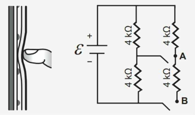
What is the equivalent resistance in the circuit caused by a touch that closes the circuit at point A?
a) 1.3 kΩ
b) 4.0 kΩ
c) 6.0 kΩ
d) 6.7 kΩ
e) 12.0 kΩ
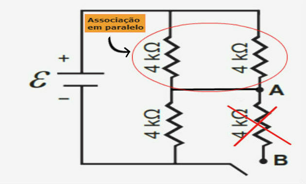
Since only switch A has been connected, then the resistance connected to terminals AB will not be working.
Thus, we have three resistors, two connected in parallel and in series with the third, as shown in the image below:
To start, let's calculate the equivalent resistance of the parallel bond, for that, we'll start with the following formula:
The equivalent resistance of the parallel association is associated in series with the third resistance. Therefore, we can calculate the equivalent resistance of this association by doing:
Req = Rparallel + R3
Replacing the resistance values, we have:
Req = 2 + 4 = 6 kΩ
Alternative: c) 6.0 kΩ
2) Fuvest - 2018
Currently, LEDs (Light Emitting Diode) are used in home lighting. LEDs are semiconductor devices that conduct electrical current in only one direction. In the figure, there is an 8 W LED (L) power supply circuit, which operates at 4 V, being powered by a 6 V (F) source.
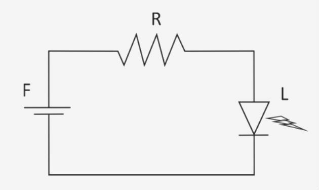
The resistor resistance value (R), in Ω, required for the LED to operate at its nominal values is approximately
a) 1.0.
b) 2.0.
c) 3.0.
d) 4.0.
e) 5.0.
We can calculate the LED resistance value through the power formula, ie:
Replacing the values indicated in the question, we have:
The current through the circuit can be found by applying the 1st Ohm's law, ie:
U = R. i
So, calculating the current that passes through the LED, we find:
Since the LED and resistor are associated in series, the current through the LED is the same throughout the circuit.
With this, we can find the equivalent resistance of the circuit, considering the value of the voltage of the source and the current of the circuit, that is:
To find the resistance value, just apply the formula for the equivalent resistance of a series circuit, that is:
Req = R + RLED
Replacing the values, we have:
3 = R + 2
R = 3 - 2 = 1 Ω
Alternative: a) 1.0.
3) Unicamp - 2018
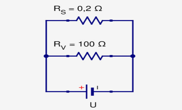
In recent years, exotic materials known as topological insulators have become the subject of intense scientific investigation around the world. In a simplified way, these materials are characterized by being electrical insulators inside, but conductors on their surface. Thus, if a topological insulator is subjected to a potential difference U, we will have a resistance effective on the surface different from the resistance of its volume, as shown by the equivalent circuit in the figure bellow. In this situation, the reason between current is that passes through the conductive portion on the surface and the current iv that crosses the insulating portion inside the material is worth
a) 0.002.
b) 0.2.
c) 100.2.
d) 500.
The resistors Rv and Rs are associated in parallel. In this type of association, all resistors are subjected to the same potential difference U.
However, the intensity of current passing through each resistor will be different, as the resistance values are different. Thus, by the 1st law of Ohm we have:
U = Rs.is and U = Rv.iv
Equating the equations, we find:
isolating iv and replacing the resistance values, we have:
To find the value of the ratio F, let's substitute iv by the expression found, that is:
Alternative: d) 500.
4) UFRGS - 2018
A voltage source whose electromotive force is 15 V has an internal resistance of 5 Ω. The source is connected in series with an incandescent lamp and a resistor. Measurements are carried out and it is verified that the electric current that passes through the resistor is 0.20 A, and that the potential difference in the lamp is 4 V. In this circumstance, the electrical resistances of the lamp and resistor are, respectively,
a) 0.8 Ω and 50 Ω.
b) 20 Ω and 50 Ω.
c) 0.8 Ω and 55 Ω.
d) 20 Ω and 55 Ω.
e) 20 Ω and 70 Ω.
In series association, the current that passes through the circuit is the same, so the current of 0.20 A also passes through the lamp. So, applying Ohm's law, we have:
We can calculate the value of the potential difference between the circuit terminals through the generator equation, that is:
The potential difference between the lamp terminals is equal to 4 V and d.d.p. of the entire circuit is equal to 14 V. So at the resistor terminals the potential difference is equal to 10 V (14-4).
Now that we know the value of d.d.p. on the resistor, we can apply Ohm's law:
Alternative: b) 20 Ω and 50 Ω.
A circuit has 3 identical resistors, two of them placed in parallel with each other, and connected in series with the third resistor and with a 12V source. The current flowing through the source is 5.0 mA. What is the resistance of each resistor, in kΩ?
a) 0.60
b) 0.80
c) 1.2
d) 1.6
e) 2.4
As we know the value of the voltage at the terminals of the circuit and the current that passes through it, we can calculate the value of the equivalent resistance by applying Ohm's law, that is:
U = R. i
Replacing the values and considering that 5.0 mA is equal to 0.005 A, we have:
The equivalent resistance of the circuit is equal to the sum of the equivalent resistance of the association in parallel with the third resistance in series.
So we need to find the equivalent resistance value of the parallel, for that, we will apply the following formula:
In this way, we can calculate the value of each resistance from the equivalent resistance value of the circuit, that is:
Alternative: d) 1.6
6) PUC/SP - 2018
Two electrical resistors, of resistors RTHE and RB, generate 500 kWh of energy, when associated in parallel and submitted to an electrical voltage of 100 V, for 100 uninterrupted hours. These same resistors, when paired in series and subjected to the same voltage, for the same period of time, generate 125 kWh of energy.
Determine, in ohm, the values of RTHE and RB, respectively:
a) 4 and 8.
b) 2 and 8.
c) 2 and 4.
d) 4 and 4.
Electric energy is given by the formula E = P. t, where P is electrical power and t is time. The potency, in turn, can be found through the expression . Therefore, we can write the energy as:
In this way, we will substitute the values for each association. In the parallel association, we have:
In series association, the equivalent resistance will be equal to:
Now that we know the value of the equivalent resistances in each of the associations, we can calculate the value of the resistances RTHE and RB applying the equivalent resistor formula.
On the Serie:
In parallel:
Replacing RTHE in this expression, we have:
Solving this 2nd degree equation, we find that RB = 4 Ω. Substituting this value to find the value of RTHE:
RTHE = 8 - RB
RTHE = 8 - 4 = 4 Ω
Alternative: d) 4 and 4.
7) Enem - 2017
Fuse is an overcurrent protection device in circuits. When the current passing through this electrical component is greater than its maximum rated current, the fuse blows. In this way, it prevents the high current from damaging the circuit devices. Assume that the electrical circuit shown is powered by a U voltage source and that the fuse supports a rated current of 500 mA.
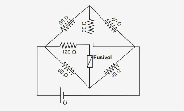
What is the maximum value of voltage U for the fuse not to blow?
a) 20 V
b) 40 V
c) 60V
d) 120V
e) 185 V
To better visualize the circuit, let's redraw it. To do this, we name each node in the circuit. Thus, we can identify what kind of association exists between resistors.
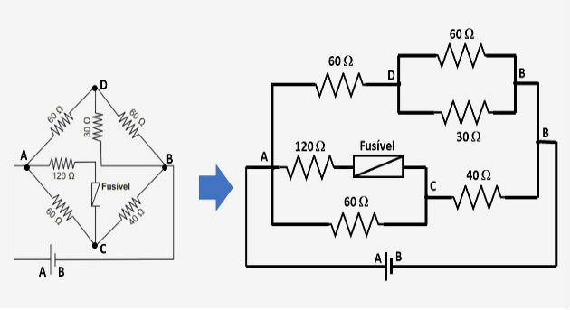
Observing the circuit, we identify that between points A and B we have two branches in parallel. At these points, the potential difference is the same and equal to the circuit's total potential difference.
In this way, we can calculate the potential difference in just one branch of the circuit. So, let's choose the branch that contains the fuse, because in this case, we know the current that passes through it.
Note that the maximum current that can travel through the fuse is equal to 500 mA (0.5 A) and that this current will also travel through the 120 Ω resistor.
From this information, we can apply Ohm's law to calculate the potential difference in this section of the circuit, ie:
UB.C = 120. 0.5 = 60V
This value corresponds to d.d.p. between points A and C, therefore, the 60 Ω resistor is also subjected to this voltage, as it is associated in parallel with the 120 Ω resistor.
Knowing the d.d.p. that the 120 Ω resistor is subjected, we can calculate the current that passes through it. For that, let's again apply Ohm's law.
So, the current that passes through the 40 Ω resistor is equal to the sum of the current that passes through the 120 resistor with that that passes through the 60 Ω resistor, that is:
i´ = 1 + 0.5 = 1.5 A
With this information, we can calculate the d.d.p. between the 40 Ω resistor terminals. So we have:
UCB = 1,5. 40 = 60V
To calculate the maximum voltage for the fuse not to blow, it will only be necessary to calculate the sum of UB.C with UCB, therefore:
U = 60 + 60 = 120 V
Alternative: d) 120 V
To learn more, see also
- Electrical Resistance
- Electric circuit
- Potential Difference
- Electric current
- Electric Current Exercises
- Association of Trainers
- Electricity
- Conductors and Insulator
- Kirchhoff's Laws
- Physics Formulas
- Physics in Enem