At Kirchhoff's laws, known as mesh law and laws of us, are, respectively, laws of conservation ofchargeelectric and of the energy in knits and knots of electric circuits. These laws were created by the German physicist GustavRobertKirchoff and are used to analyze complex electrical circuits, which cannot be simplified.
See more: What causes lightning strikes? Access and understand what is rupture of dielectric strength
Introduction to Kirchhoff's Laws
To learn how to use the lawsinKirchoff, we need to understand what the we,branches and knits of electrical circuits. Let's check a simple and objective definition of each of these concepts:
We: are where there are branches in the circuits, that is, when there is more than one path for the passage of the electric current.
Branches: are the sections of the circuit that lie between two consecutive nodes. Along a branch, electrical current is always constant.
Knits: they are closed paths where we start at a node and return to the same node. In a mesh, the sum of the electrical potentials is always equal to zero.
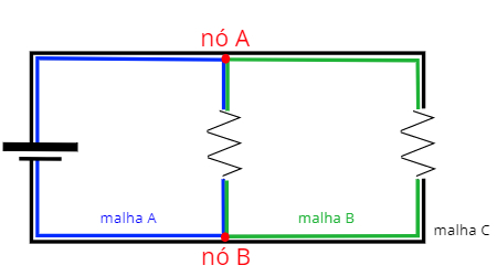
In the following figure we show a circuit that presents nodes, branches and meshes, check:

Kirchhoff's 1st law: law of knots
According to Kirchoff's laws, the sumof all the currents that come to a knot of the circuit must be equal to the sum of all currents leaving that same node.. This law is a consequence of the principle of conservation of electrical charge. According to him, regardless of the phenomenon, the initial electrical charge will always be equal to the final electrical charge of the process.
It is noteworthy that the electric current is a scalar greatness and therefore, has no direction or meaning. Thus, when we add the intensities of electrical currents, we only take into account if the current arrive or leave the knot.
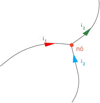
Check the figure below, in it we apply Kirchhoff's 1st law to incoming electrical currents that leave a knot:

Kirchhoff's 2nd law: mesh law
Kirchhoff's second law states that sumFrompotentialselectric along a closed loop must be equal to zero. Such law stems from energy conservation principle, which implies that all energy supplied to the mesh of a circuit is consumed by the elements present in that mesh.
Formally, Kirchhoff's 2nd law is written as a summation of all electrical potentials, as shown in this figure:

The sum of the N currents arriving and leaving a node in the circuit is equal to 0.
See too: How much does it cost to recharge your cell phone battery? We did the calculations for you!
You potentialselectric From resistors of the mesh shall be calculated by the resistances of each of these elements, multiplied by the electrical current that passes through them, in line with the 1st law of Ohm:

U – voltage or electrical potential (V)
R – electrical resistance (Ω)
i – electric current (A)
If the traversed mesh contains other elements, such as generators or receivers, we need to know how to identify them, since the symbols used to represent generators and receivers they are equals. Therefore, we observe the electric current direction that runs through these elements, remembering that, for both generators and receivers, the long bar represents the potentialpositive, while the smaller bar represents the potentialnegative:
the generators they are always carried by an electric current that enters through the negative terminal, with less potential, and leaves through the positive terminal, with greater potential. In other words, when passing through the generator, the electric current undergoes an increase in potential or gains energy.
the receivers they are traversed by an electric current that enters the positive terminal and leaves the negative terminal, so that the electric current “loses” energy as it travels through them.
Do not stop now... There's more after the advertising ;)
After learning to identify the generators and receivers of the mesh, it is necessary to understand how the sign convention of Kirchhoff's 2nd Law. Check out the steps:
Choose an arbitrary direction for the electric current: in case you do not know the direction in which the electric current flows through the circuit, just choose one of the directions (clockwise or counterclockwise). If the current direction is different, you will simply get a current with a negative sign, so don't worry so much about getting the direction right.
Choose a direction for the mesh to circulate: just as we did for the electric current, we'll do it for the direction in which the mesh is traversed: choose an arbitrary direction to traverse each mesh.
Add the electrical potentials: if you run a resistor in favor of the electric current, the sign of the electric potential will be positive, if the crossed resistor is crossed by an electrical current in the opposite direction, use the negative sign. When passing through a generator or receiver, note which terminal you go through first: if it's the negative terminal, the electrical potential must be negative, for example.
Know more: Resistor association - what is it, types and formulas
Example of Kirchhoff's Laws for Electrical Circuits
Let's check out an application of Kirchoff's laws. In the next figure, we will show an electrical circuit that contains three meshes, A, B and C:

Now, we show each of the loops of the circuit separately:

In the following figure, we will show how the direction in which the meshes are traveled was chosen, as well as the arbitrated direction for the electric current:

In addition to being used to define the direction in which we will go through the meshes, the previous figure defines that the electric current that arrives at node A, iT, is equal to the sum of the currents i1 and i2. Therefore, according to Kirchhoff's 1st law, the electric current at node A obeys the following relationship:

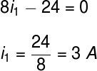
After we get the previous relationship, we will apply the Kirchoff's 2nd Law at meshes A, B and C. Starting with mesh A and running clockwise from node A, we pass through a resistor of 8 Ω, flown by a current i1 also in the senseschedule, therefore, the potentialelectric in this element is simply 8i1. Then we find the terminalnegative 24 V, which will thus have signalnegative:

After we have obtained the electric current i1, based on the application of Kirchhoff's 2nd law in mesh A, we will do the same process in mesh B, starting from node A, also clockwise:

With the first equation we obtained, through Kirchhoff's 1st law, we can determine the current intensity iT:

Note that for the circuit used as an example it was not necessary to determine the equation of the outer loop C, however some slightly more complex circuits require us to determine the equations of all the meshes and are usually solved by methods. in scaling, for the Cramer's rule or by others solving methods of linear systems.
Also access: Relationship between matrix and linear systems
Exercises on Kirchhoff's Laws
Question 1) (Espcex - Aman) The drawing below represents an electrical circuit composed of ohmic resistors, an ideal generator and an ideal receiver.

The electrical power dissipated in the 4 Ω resistor of the circuit is:
a) 0.16W
b) 0.20 W
c) 0.40 W
d) 0.72 W
e) 0.80 W
Template: Letter a
Resolution:
To find the power dissipated in the resistor, we need to calculate the electrical current flowing through it. For this, we will use Kirchhoff's 2nd law, traversing the circuit in a clockwise direction.

The sign we found in the answer indicates that the direction of the current we adopt is contrary to the real direction of the current, therefore, to calculate the potency dissipated in the resistor, just use the power formula:

Based on the calculations, the exercise answer is 0.16 W. Therefore, the correct alternative is the letter a".
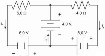
Question 2) (Udesc) According to the figure, the values of electrical currents i1, i2 Hey3 are, respectively, equal to:

a) 2.0 A, 3.0 A, 5.0 A
b) -2.0 A, 3.0 A, 5.0 A
c) 3.0 A, 2.0 A, 5.0 A
d) 5.0 A, 3.0 A, 8.0 A
e) 2.0 A, -3.0 A, -5.0 A
Template: Letter a
Resolution:
Let's solve the mesh on the left using Kirchhoff's 2nd law, to do so, we'll go through the meshes clockwise:

Next, we will apply the same law to the mesh on the right, traversing it in the same direction:

Finally, observing the node from which the current i immerses3, you can see that the currents i1 Hey2, therefore, according to Kirchhoff's 1st law, we can write that these two currents added together equal current i3:

Based on the results obtained, we realized that the currents i1, i2 Hey3 are, respectively, equal to 2.0, 3.0 and 5.0 A. Thus, the correct alternative is the letter “a”.
By Rafael Hellerbrock
Physics teacher

