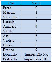
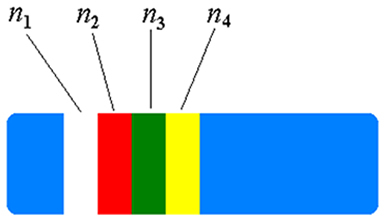
As resistors are very small components and should have their resistance values easily identified, it is customary to encode this value using a series of colored bands in the body of the resistor. Each color represents a digit. To read the resistance value code printed on the resistor we must consider that:
1. Colored bands are read from the one closest to an edge.
2. The first colored band represents the first digit of the resistance value.
3. The second colored band indicates the second digit.
4. The third band represents the power of ten by which we must multiply the two digits.
5. The fourth range, which is optional, indicates inaccuracy in the resistance value. Silver indicates 10% inaccuracy, gold indicates 5% and the absence of this band represents 20% inaccuracy.
In the table below are the colors and their respective values.
Do not stop now... There's more after the advertising ;)

A resistor, colored white, red and green, will have a resistance of 92 x 105 Ω. A 47 Ω resistor, with 5% inaccuracy, will have the colors: yellow, violet, black and gold.

Resistors are not manufactured with all resistance values, but only with a discrete set of values. Intermediate values can be achieved with the association of resistors, when necessary, or with the use of variable resistors, such as potentiometers. Although the name suggests that this would be a device to measure power, it is nothing more than a resistor that can be adjusted. These are the components used to control the volume of sound in amplifiers.
By Domitiano Marques
Graduated in Physics
Would you like to reference this text in a school or academic work? Look:
SILVA, Domitiano Correa Marques da. "Color code for resistors"; Brazil School. Available in: https://brasilescola.uol.com.br/fisica/codigo-cores-para-resistores.htm. Accessed on June 27, 2021.


